Ich habe nicht noch über microbiological Analysis gesprochen. In diese video sie können sehen wie ist Sicherheit im Trinkwasser kontrolliert worden. Pflege für die Prophylaxe in Arbeitsplatz!
Sonntag, 16. September 2012
Mittwoch, 12. September 2012
So überprüfen (7)
Messen mit dem Messschieber
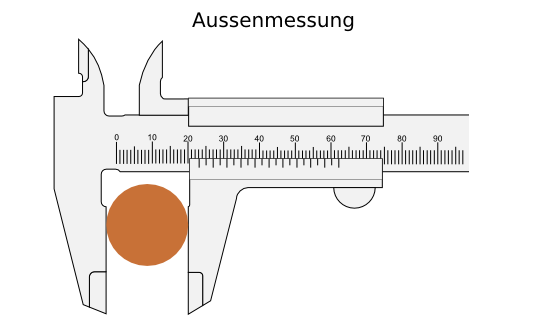 Der Messschieber wird am häufigsten für die Aussenmessung verwendet. Bei der Messung von Aussenmassen besteht die Gefahr von Messfehlern durch das Abkippen des Messchenkels. Aus diesem Grunde sollte der Prüfgegenstand möglichst nahe an der Schiene anliegen. Die Schneiden der Messschenkel nur dort verwendet
werden, wo der Prüfgegenstand deren Anwendung erzwingt.
Der Messschieber wird am häufigsten für die Aussenmessung verwendet. Bei der Messung von Aussenmassen besteht die Gefahr von Messfehlern durch das Abkippen des Messchenkels. Aus diesem Grunde sollte der Prüfgegenstand möglichst nahe an der Schiene anliegen. Die Schneiden der Messschenkel nur dort verwendet
werden, wo der Prüfgegenstand deren Anwendung erzwingt.
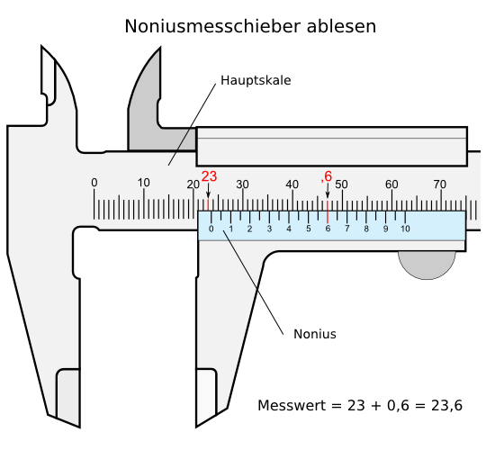
Wenn man sich einen
Messschieber ansieht, erkennt man
auf diesem zwei verschiedene Skalen: Eine große Skala (Hauptskale) über die
gesamte Länge des Messschiebers und eine kurze Skala unter der Hauptskale
(Nonius). Das Ablesen des Wertes auf der Hauptskale ist einfach. Der gemessene
Wert lässt sich an der Stelle ablesen, die der Ziffer 0 am Nonius gegenübersteht.
Im vorliegenden Beispiel sind das 23 Millimeter und ein Bruchteil eines
Millimeters. Die genaue Größe dieses Bruchteiles lässt sich aber auf der
Hauptskale nicht genau ablesen. Der Maßstab ist zu klein.
Hier hilft nun der
Nonius zur Hilfe. Wie mit einer Lupe lässt sich mit dieser
Hilfseinrichtung bequem der genaue Wert dieses Bruchteiles am Nonius
ermitteln.
Hierzu liest man auf dem Nonius den Wert ab, der einem Millimeterstrich auf der
Hauptskale genau gegenübersteht. Dieser Wert (im vorliegenden Beispiel 6) ist
der Wert nach dem "Komma", d.h. 0,6 mm (bei einem 1/10 Nonius) und ist zu den, an der
Hauptskale abgelesenen, ganzen Millimetern zu addieren. Im vorliegenden
Beispiel sind das dann 23mm (Hauptskale) + 0,6 mm = 23,6 mm.
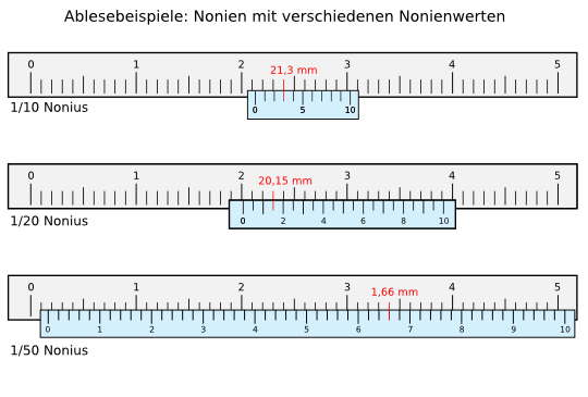
Die Striche auf der Hauptskale und die Striche auf dem Nonius stehen in einem genau
definiertem Verhältnis zueinander. Im Falle unseres Beispieles sind das 9:10,
d.h. der Abstand zwischen zwei Strichen auf dem Nonius sind 0,9 mm, auf der
Hauptskale hingegen jeweils 1 mm. Durch dieses Verhältnis wird es beim
Verschieben des Nonius gegen die Hauptskale immer einen Strich auf dem Nonius
geben, der einem Strich auf der Hauptskala gegenübersteht, d.h. bei dem die
Summe des Messwertes und des Noniuswertes ein Vielfaches von 1 ist. Bei einem
Bruchteil von 0,1 mm ist dies die 1 auf dem Nonius (0,1 Messwert + 0,9mm - Abstand
zwischen zwei Strichen auf dem Nonius), bei einem Bruchteil von z.B. 0,3 mm = 0,3
mm Messwert + 3 x 0,9 mm (0,27 mm) ist dies die 3 auf dem Nonius usw.
So überprüfen (6)
Die Messschraube
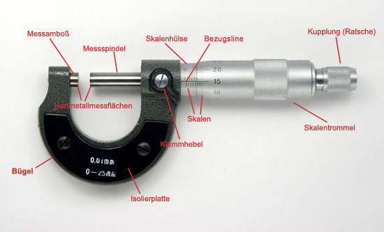
Richtiges Messen mit der Messschraube
Das zu messende Werkstück wird zwischen Amboss und
Messspindel gehalten. Um möglichst zuverlässige Messwerte zu erhalten,
wird die Messspindel ohne Schwung mit der Kupplung (Ratsche) eingedreht.
Die Kupplung hat die Aufgabe, die Messkraft auf 5-10 N zu begrenzen.
Der Bügel der Messschraube sollte bei der Messung nur an der
Isolierplatte angefasst werden, da die Handwärme das Messergebnis sonst
verfälschen würde. Trotz der Isolierplatte kann die Handwärme zu einer
Abweichung des Messergebnisses um bis zu 0,002 mm führen.
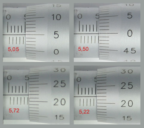
Richtiges Ablesen der Skala an der analogen Messschraube
Die Spindel der Messschraube hat üblicherweise eine
Steigung von 0,5 mm. Bei einer Umdrehung der Skalentrommel wird die
Messspindel axial um einen halben Millimeter gedreht. Auf der
Skalentrommel sind 50 Teilstriche angebracht. Jeder Teilstrich
entspricht demnach 0,01 mm. Auf der Skalenhülse sind oberhalb der
Bezugslinie Teilstriche für die vollen Millimeter und unterhalb die
Teilstriche für die halben Millimeter angebracht.
Dienstag, 11. September 2012
Aluminium anodizing
Anodizing, What is it?

Here is detailed information comparing two of the most common coloring processes used: (note - these two types of processes will not produce identical colors; both can be overdyed. Source: Aluminum Anodizers Council Technical Bulletin #1-94, issued January, 1994.) See below.
Anodizing successfully combines science with nature to create one of the world's best metal finishes.
It is an electrochemical process that thickens
and toughens the naturally occurring protective oxide. The resulting
finish, depending on the process, is the second hardest substance known
to man, second only to the
diamond. The anodic coating is part of the metal, but has a porous
structure which allows secondary infusions, (i.e. organic and inorganic
coloring, lubricity aids, etc.)
Anodizing Definitions and Methods
While the chemical anodizing process remains the same
for all applications, the mechanical methods vary according to the two
physical types and shapes of metals used:
|
Appearance options and quality are improved
through the use of dyes and special pretreatment procedures. This makes
the aluminum look like pewter, stainless steel, copper, brushed bronze
or polished brass and can also be
colored with brilliant blues, greens, reds, and many varieties of
metallic gold and silver.
The unique dielectric properties of an anodized finish offer many opportunities for electrical applications.
The surface of the aluminum itself is toughened
and hardened to a degree unmatched by any other process or material. The
coating is 30 percent thicker than the metal it replaces, since the
volume of oxide produced is
greater than that of the metal replaced.
The resulting anodic coating is porous, allowing relatively easy coloring and sealing.
Hard Anodizing is a
term used to describe the production of anodic coatings with film
hardness or abrasion as their primary characteristic. They are usually
thick by normal anodizing standards
(greater than 25 microns) and they are produced using special
anodizing conditions (very low temperature, high current density,
special electrolytes). They find application in the engineering industry
for components which
require a very wear resistant surface such as piston,
cylinders and hydraulic gear. They are often left unsealed, but may be
impregnated with materials such as waxes or silicone fluids to give
particular surface properties.
Batch and Coil Anodizing
Batch and coil anodizing are accomplished in five carefully controlled, calibrated, quality-tested stages:
1. Cleaning. Alkaline and/or acid cleaners remove grease, and surface dirt.
2. Pre-Treatment
- Etching. An appealing matte surface finish is created with hot solutions of sodium hydroxide to remove minor surface imperfections. A thin layer of aluminum is removed to create a matte or dull finish.
- Brightening. A near mirror finish is created with a concentrated mixture of phosphoric and nitric acids which chemically smooths the aluminum's surface.
3. Anodizing. The anodic film
is built and combined with the metal by passing an electrical current
through an acid electrolyte bath in which the aluminum is immersed. The
coating thickness and surface
characteristics are tightly controlled to meet end product
specifications.
4. Coloring. Coloring is achieved in one of four ways:
- Electrolytic Coloring (The two-step method) - After anodizing, the metal is immersed in a bath
containing an inorganic metal salt. Current is applied which deposits the metal salt in the base of the pores. The resulting color is dependent on the metal used and the processing conditions (the range of colors can be expanded by overdyeing the organic dyes). Electrolytic colors can be specified from any AAC member. Commonly used metals include tin, cobalt, nickel, and copper. This process offers color versatility and the most technically advanced coloring quality.
- Integral Coloring - This so-called one-step process combines anodizing and coloring to simultaneously form and color the oxide cell wall in bronze and black shades while more abrasive resistant than conventional anodizing. It is the most expensive process since it requires significantly more electrical power.
- Organic Dyeing - The organic dyeing process produces a wide variety of colors. These dyes offer vibrant colors with intensities that cannot be matched by any other paint system in the market. They can also provide excellent weather-fastness and light-fastness. Many structures built with these finishes have lasted more than 20 years. The color range can be broadened by over-dyeing the electrolytic colors with the organic dyes for a wider variety of colors and shades. This method is relatively inexpensive and involves the least amount of initial capital of any other coloring process.
- Interference Coloring - An additional coloring procedure, recently in production, involves modification of the pore structure produced in sulfuric acid. Pore enlargement occurs at the base of the pore. Metal deposition at this location produces light-fast colors ranging from blue, green and yellow to red. The colors are caused by optical-interference effects, rather than by light scattering as with the basic electrolytic coloring process. Further development will produce a greater variety of colors.
Here is detailed information comparing two of the most common coloring processes used: (note - these two types of processes will not produce identical colors; both can be overdyed. Source: Aluminum Anodizers Council Technical Bulletin #1-94, issued January, 1994.) See below.
5. Sealing. This process closes
the pores in the anodic film, giving a surface resistant to staining,
abrasion, crazing and color degradation.
Quality control. Throughout the entire anodizing
process, AAC members monitor the process and quality of the product. The
application of electrical power and color is preprogrammed and verified
on all batches and coils.
This quality control ensures uniformity to end
product specifications for film thickness, density, abrasion resistance,
corrosion resistance, color uniformity, fade resistance, reflectivity,
image clarity, insulative properties,
adhesion and sealing.
In many cases, AAC members use Statistical Process Control (SPC) methods to meet rigorous quality assurance standards.
Comparison of A32/A42 and A34/A44 Colored Aluminum Anodic Finishes
| A32 & A42 | A34 & A44 | |
|---|---|---|
Generic Names
|
Integral One Step Architectural Hardcoat |
Electrolytic Coloring Two Step |
Representative Trade Names
|
Duranodic Kalcolor Permanodic |
Anolok Sandocolor Colormax |
Colors
|
Champagnes, Bronzes, Blacks, Grays | Champagnes, Bronzes, Blacks, Pinks, Burgundies |
Exterior Durability
|
Excellent | Excellent |
Color Match
|
Good | Excellent |
Color Reproducibility
|
Good | Excellent |
Alloy Sensitivity
|
High | Low |
Cost to Produce
|
Moderate | Low |
Energy Required to Produce
|
High | Low |
Availability-Batch Processing
|
Limited | Low |
Availability-Coil Processing
|
Unavailable | Low |
Montag, 10. September 2012
Abonnieren
Posts (Atom)